Home
Contents

Program for dataloggers online manual

Prev Page Next Page
 
Program for dataloggers
Reference guide
Program handling
Language
Main menu
Main toolbar
Main toolbar (free version)
Program options
Data storing
Communication
Communication interface USB/RS232
Communication interface RS232 (ATD series)
Communication interface Ethernet
Communication interface Modem
Data presentation
M2M connection
Autodownload
Datalogger database
Device settings
Datalogger settings
General settings
Channels settings
Display
ATD series settings
Information
General settings
Channels settings
ATP serie settings
General settings
Channels settings
Display
Data handling
Table
Graph
Graph canvas
Series list
Options
Toolbar
Graph (free version)
Graph parameters
Axes settings
Printing
Printing (freeware version)
M2M modem
Modem configuration (connection Modem to M2M server)
Practice guide
How to connect device
How to startup program with parameter
Channels settings

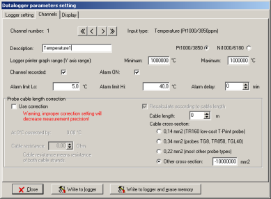
Channels parameters settings. Use arrow buttons for moving among channels ( first, previous, next, last).


Information

Channel number
Information about current channel number.


Parameters settings

Description
Channel description (name).

Input type settings

  • Pt1000/3850
  • Ni1000/6180

Logger printer graph range (Y axis range)
Y axis range of the internal logger printer graph. Set range from the Minimum to Maximum.

Channel recorded
Switch on/off recording of the selected channel. Measurement is still working until you switch off the device.

Alarm ON
Switch on/off alarm evaluation on the selected channel.

Alarm limit Lo
Write lower limit for alarm evaluation. Whenever measured value decreases under this limit, alarm is activated (alarm must be enabled).

Alarm limit Hi
Write upper limit for alarm evaluation. Whenever measured value exceedes over this limit, alarm is activated (alarm must be enabled).

Alarm delay
Alarm delay time in minutes. If zero value is set, alarm is valid immediately after value is exceeded over the limit. If higher value then zero is set, alarm becomes valid only as though measured value is behind the limit all the defined time.


Probe cable length correction

Cabel length may have effect on accuracy of measurement (line wire resistance implicate additive error). It is possible to apply correction of measurement values according to demand occuracy of measurement. Attention! Wrong correction can evaluate poor accuracy of measurement.

Enable cabel length correction by option Use correction and set correction parameters. You may use correction by line wire resistance (option Cable resistance) or by cabel length (option Recalculate according to cabel length - you may find more information in the technical manual of the temperature probe).